Blind Flange
Standard Specification For blind flange
- Dimensions :ANSI B16.5, ANSI B16.47 Series A & B, MSS SP44, ASA, API-605, AWWA, Custom Drawings
- Size :1/2″ (15 NB) to 48″ (1200NB)
- Class :150 LBS, 300 LBS, 600 LBS, 900 LBS, 1500 LBS, 2500 LBS, DIN Standard ND-6,10, 16, 25, 40 Etc.
- DIN :DIN 2527, DIN 2566, DIN 2573, DIN 2576, DIN 2641, DIN 2642, DIN 2655, DIN 2656, DIN 2627, DIN 2628, DIN 2629, DIN 2631, DIN 2632, DIN 2633, DIN 2634, DIN 2635, DIN 2636,DIN 2637, DIN 2638, DIN 2673
- BS : BS 4504 , BS 4504, BS 1560, BS 10
- PN :PN6, PN10, PN16, PN25, PN40
- Flange Face Type : Flate Face (FF), Raised Face (RF), Ring Type Joint (RTJ)
Packaging of Flanges
Packaging: Blind Flanges is sleeved into plastic bag individually, ten pieces wrapped with water-proof material, bundled with nylon rope. Clear labels are tagged on the outside of the package for easy identification of the quantity and product I.D. Great care is taken during operation and transportation.
Prevent any damage.
During transportation items are tagged, packed in plastic bags and closed in carton boxes or seaworthy wooden cases.
plywood case,pallet and according to customer’s requirment
Marking:Blind Flanges are marked with alloy name, outside diameter, wall thickness and heat number. Additional information like standard and alloy numbers can be added on request.
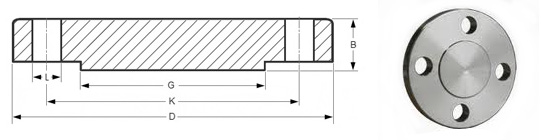
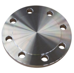
blind flange It is used to terminate the end of a piping system. The blind flange is basically a flange that does not have a hub or a bored center. Blind flanges have the face thickness of a flange, a matching face type, and similar bolting pattern. Blind flanges can also be used to seal a nozzle opening on a pressure vessel.
Material & Grades of Blind Flange :
- Stainless Steel Blind Flange : ASTM A 182, A 240 F 304, 304L, 304H, 316, 316L, 316Ti, 310, 310S, 321, 321H, 317, 347, 347H, 904L Blind Flange
- Duplex & Super Duplex Steel Blind Flange : ASTM A182 / ASME SA182 F44, F 45, F51, F 53, F 55, F 60, F 61 Blind Flange
- Carbon Steel Blind Flange : ASTM A105 / ASME SA105 ASTM / ASME A 350 , ASTM A181 LF2 / A516 Gr.70 A36, A694 F42, F46, F52, F60, F65, F706 Blind Flange
- Low Temperature Carbon Steel Blind Flange: ASTM A350, LF2, LF3 Blind Flange
- Alloy Steel Blind Flange : ASTM A182 / ASME SA182 & A387 F1, F5, F9, F11, F12, F22, F91 Blind Flange
- Copper Alloy Steel Blind Flange : ASTM SB 61 , SB62 , SB151 , SB152 UNS No. C 70600 (Cu-Ni 90/10), C 71500 (Cu-Ni 70/30), UNS No. C 10100, 10200, 10300, 10800, 12000, 12200
- Nickel Alloy Blind Flange : ASTM SB564, SB160, SB472, SB162 Nickel 200 (UNS No. N02200), Nickel 201 (UNS No. N02201), Monel 400 (UNS No. N04400), Monel 500 (UNS No. N05500), Inconel 800 (UNS No. N08800), Inconel 825 (UNS No. N08825), Inconel 600 (UNS No. N06600), Inconel 625 (UNS No. N06625), Inconel 601 (UNS No. N06601), Hastelloy C 276 (UNS No. N10276), Alloy 20 (UNS No. N08020) Blind Flange
Application of Blind Flange
- ANSI B16.5 Class 150 Blind Flange uses in Industrial Boilers Industry
- ASTM A182 Stainless Steel Blind Flange uses in Power Plants Industry
- ASME B16.47 Series A and B Blind Flange uses in Nuclear Plants Industry
- Stainless Steel Blind Flange uses in Oil & Gas Industry
- Super Duplex Steel Blind Flange uses in Refineries Industry
- Industrial Blind Flange uses in Ship Building Industry
- Super Duplex Steel Blind Flangea Forged Flange uses in Heat Exchanger Industry
- Carbon Steel Industrial Blind Flange uses in Condensers Industry
- Alloy Steel Industrial Blind Flange uses in Paper & Pulp Industry
- Duplex Steel Industrial Blind Flange uses in Marine Applications
- Stainless Steel Industrial Blind Flange uses in Nuclear Power Industry
- Industrial Blind Flangea / Fittings System uses in Fossil Fuel Power Plants Industry
blind flange dimensions of ASME B16.11
ANSI/ASME/ASA B16.5 150lb/sq.in. Flange BLIND-RF | |||||||
ø | D | b | g | k | Holes | l | Kg. |
1/2″ | 88,9 | 11,1 | 34,9 | 60,3 | 4 | 15,9 | 0,400 |
3/4″ | 98,4 | 12,7 | 42,9 | 69,8 | 4 | 15,9 | 0,700 |
1″ | 107,9 | 14,3 | 50,8 | 79,4 | 4 | 15,9 | 0,900 |
1 1/4″ | 117,5 | 15,9 | 63,5 | 88,9 | 4 | 15,9 | 1,300 |
1 1/2″ | 127,0 | 17,5 | 73,0 | 98,4 | 4 | 15,9 | 1,600 |
2″ | 152,4 | 19,0 | 92,1 | 120,6 | 4 | 19,0 | 2,600 |
2 1/2″ | 177,8 | 22,2 | 104,8 | 139,4 | 4 | 19,0 | 4,100 |
3″ | 190,5 | 23,8 | 127,0 | 152,4 | 4 | 19,0 | 5,000 |
3 1/2″ | 215,9 | 23,8 | 139,7 | 177,8 | 8 | 19,0 | 6,400 |
4″ | 228,6 | 23,8 | 157,2 | 190,5 | 8 | 19,0 | 7,100 |
5″ | 254,0 | 23,8 | 185,7 | 215,9 | 8 | 22,2 | 9,000 |
6″ | 279,4 | 25,4 | 215,9 | 241,3 | 8 | 22,2 | 11,800 |
8″ | 342,9 | 28,6 | 269,9 | 298,4 | 8 | 22,2 | 21,000 |
10″ | 406,4 | 30,2 | 323,4 | 361,9 | 12 | 25,4 | 30,000 |
12″ | 482,6 | 31,7 | 381,0 | 431,8 | 12 | 25,4 | 45,000 |
14″ | 533,4 | 34,9 | 412,7 | 476,2 | 12 | 28,6 | 59,000 |
16″ | 596,9 | 36,5 | 469,9 | 539,9 | 16 | 28,6 | 79,000 |
18″ | 635,0 | 39,7 | 533,4 | 577,8 | 16 | 31,7 | 97,000 |
20″ | 698,5 | 42,9 | 584,2 | 635,0 | 20 | 31,7 | 124,000 |
22″ | 749,3 | 46,0 | 641,2 | 692,1 | 20 | 34,9 | 151,000 |
24″ | 812,8 | 47,6 | 692,1 | 749,3 | 20 | 34,9 | 188,000 |
ANSI/ASME/ASA B16.5 300lb/sq.in. Flange BLIND-RF | |||||||
ø | D | b | g | k | Holes | l | Kg. |
1/2″ | 95,2 | 14,3 | 34,9 | 66,7 | 4 | 15,9 | 0,700 |
3/4″ | 117,5 | 15,9 | 42,9 | 82,5 | 4 | 19,0 | 1,200 |
1″ | 123,8 | 17,5 | 50,8 | 88,9 | 4 | 19,0 | 1,500 |
1 1/4″ | 133,3 | 19,0 | 63,5 | 98,4 | 4 | 19,0 | 2,000 |
1 1/2″ | 155,6 | 20,6 | 73,0 | 114,3 | 4 | 22,2 | 2,900 |
2″ | 165,1 | 22,2 | 92,1 | 127,0 | 8 | 19,0 | 3,400 |
2 1/2″ | 190,5 | 25,4 | 104,8 | 149,2 | 8 | 22,2 | 5,100 |
3″ | 209,5 | 28,6 | 127,0 | 168,3 | 8 | 22,2 | 7,000 |
3 1/2″ | 228,6 | 30,2 | 139,7 | 184,1 | 8 | 22,2 | 8,900 |
4″ | 254,0 | 31,7 | 157,2 | 200,0 | 8 | 22,2 | 11,800 |
5″ | 279,4 | 34,9 | 185,7 | 234,9 | 8 | 22,2 | 15,500 |
6″ | 317,5 | 36,5 | 215,9 | 269,9 | 12 | 22,2 | 21,300 |
8″ | 381,0 | 41,3 | 269,9 | 330,2 | 12 | 25,4 | 35,200 |
10″ | 444,5 | 47,6 | 323,8 | 387,3 | 16 | 28,6 | 57,000 |
12″ | 520,7 | 50,8 | 381,0 | 450,8 | 16 | 31,7 | 82,000 |
14″ | 584,2 | 54,0 | 412,7 | 514,3 | 20 | 31,7 | 106,000 |
16″ | 647,7 | 57,1 | 469,9 | 571,5 | 20 | 34,9 | 140,000 |
18″ | 711,2 | 60,3 | 533,4 | 628,6 | 24 | 34,9 | 178,000 |
20″ | 774,7 | 63,5 | 584,2 | 685,8 | 24 | 34,9 | 223,000 |
22″ | 838,2 | 66,7 | 641,2 | 742,9 | 24 | 41,3 | 270,000 |
24″ | 914,4 | 69,8 | 692,1 | 812,8 | 24 | 41,3 | 345,000 |
ANSI/ASME/ASA B16.5 600lb/sq.in. Flange BLIND-RF | |||||||
ø | D | b | g | k | Holes | l | Kg. |
1/2″ | 95,2 | 14,3 | 34,9 | 66,7 | 4 | 15,9 | 0,700 |
3/4″ | 117,5 | 15,9 | 42,9 | 82,5 | 4 | 19,0 | 1,200 |
1″ | 123,8 | 17,5 | 50,8 | 88,9 | 4 | 19,0 | 1,500 |
1 1/4″ | 133,3 | 20,6 | 63,5 | 98,4 | 4 | 19,0 | 2,000 |
1 1/2″ | 155,6 | 22,2 | 73,0 | 114,3 | 4 | 22,2 | 3,200 |
2″ | 165,1 | 25,4 | 92,1 | 127,0 | 8 | 19,0 | 4,300 |
2 1/2″ | 190,5 | 28,6 | 104,8 | 149,2 | 8 | 22,2 | 6,000 |
3″ | 209,5 | 31,7 | 127,0 | 168,3 | 8 | 22,2 | 8,000 |
3 1/2″ | 228,6 | 34,9 | 139,7 | 184,1 | 8 | 25,4 | 10,500 |
4″ | 273,0 | 38,1 | 157,2 | 215,9 | 8 | 25,4 | 18,000 |
5″ | 330,2 | 44,4 | 185,7 | 266,7 | 8 | 28,6 | 28,500 |
6″ | 355,6 | 47,6 | 215,9 | 292,1 | 12 | 28,6 | 35,500 |
8″ | 419,1 | 55,6 | 269,9 | 349,2 | 12 | 31,7 | 58,000 |
10″ | 508,0 | 63,5 | 323,8 | 431,8 | 16 | 34,9 | 98,000 |
12″ | 558,8 | 66,7 | 381,0 | 488,9 | 20 | 34,9 | 125,000 |
14″ | 603,2 | 69,8 | 412,7 | 527,0 | 20 | 38,1 | 151,000 |
16″ | 685,8 | 76,2 | 469,9 | 603,2 | 20 | 41,3 | 215,000 |
18″ | 742,9 | 82,5 | 533,4 | 654,0 | 20 | 44,4 | 287,000 |
20″ | 812,8 | 88,9 | 584,2 | 723,9 | 24 | 44,4 | 366,000 |
22″ | 869,9 | 95,2 | 641,2 | 777,9 | 24 | 47,6 | 437,000 |
24″ | 939,8 | 101,6 | 692,1 | 838,2 | 24 | 50,8 | 532,000 |
Dimensional Tolerances of Blind Flange ASME B16.5
| Outside Diameter ≤ 24 = 1.6 mm | > 24 = ± 3.2 mm | Inside Diameter not applicable |
| Diameter of Contact Face 1.6 mm Raised Face = ± 0.8 mm 6.35 mm Raised Face, Tongue & Groove / Male-Female = ± 0.4 mm | Outside Diameter of Hub ≤ 12 = + 2.4 mm / – 1.6 mm | ≥ 14 = ± 3.2 mm |
| Diameter of Counterbore not applicable | Drilling Bolt Circle = 1.6 mm | Bolt Hole Spacing = ± 0.8 mm Eccentricity of Bolt Circle with Respect to Facing ≤ 2½ = 0.8 mm max. | ≥ 3 = 1.6 mm max. |
| Thickness ≤ 18 = + 3.2 mm / – 0 | ≥ 20 = + 4.8 mm / – 0 | Length thru Hub ≤ 18 = + 3.2 mm / – 0.8 mm | ≥ 20 = + 4.8 mm / – 1.6 mm |
Notes
1. Dimensions are in millimeters unless otherwise indicated.
2. The length of the stud bolt does not include the height of the chamfers (points).
INDUSTRIES WE CATERS INDUSTRIAL FORGE FITTING
- Ronak Overseas has many years of experiance of export and supply of ASME B16.11 Forged Fittings that is extensively used in the following industries:
- Refineries
- Gas Processing
- Off-Shore Oil Drilling Companies
- Petrochemicals
- Hydro-Carbon
- Fertilizers
- Paper & Pulp Companies
- Power Generation
- Specialty Chemicals
- Pharmaceuticals
- Drugs
- Steel
- Cement
- Water Pipe Line
- Pesticides
- General Piping
- Construction
- Engineering
- Nuclear
- Food Processing & Dairy
- boiler & heatexchangers